This is a bit of a write up and documentation about a shader experiment I did a few weeks ago, so here we go.
To recall what this actually looked like, here the original outcome.
Principle
What you are looking at is not a fluid simulation.
That comes to no surprise, as high fidelity simulation of liquids on current consumer graphics hardware at interactive frame rates might still be a couple of years away.
So what I built is something that emulates the same outcome, based on a whole lot of assumptions and constraints, that will make the result look kinda like it’s the real thing.
This write-up is not a step-by-step tutorial, more a train of thought to potentially get your own inspirations going on how to implement a system like this by yourself.
I’ve coded this demo in Unity – it would work in any other platform that allows you to render anything with a custom shader.
This shader is used to figure out what color the pixels need to have, when looking at the sphere. That in return is done by a a simple ray marching algorithm to “look inside the sphere” to find out.
But let’s start at the beginning.
Setup
Let’s start with the base shape.
My initial inspiration to attempt this came from Ryan Brooks (@shaderbits) amazing tech demo with the liquid in a bottle.
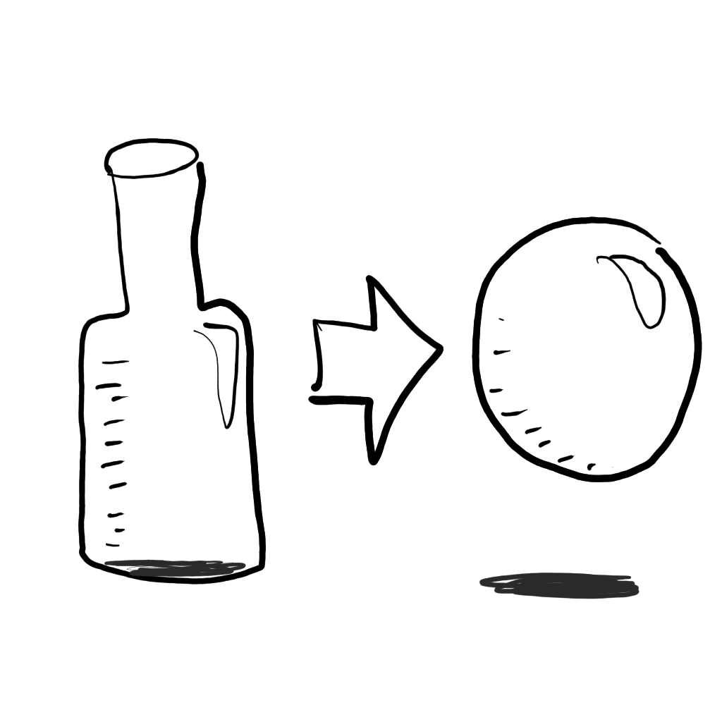
But I did not find myself with a lot of spare time, so I swapped the more complex bottle shape to something that is analytically simplifying all the steps that have to follow later.
I made the glass container to be a sphere.
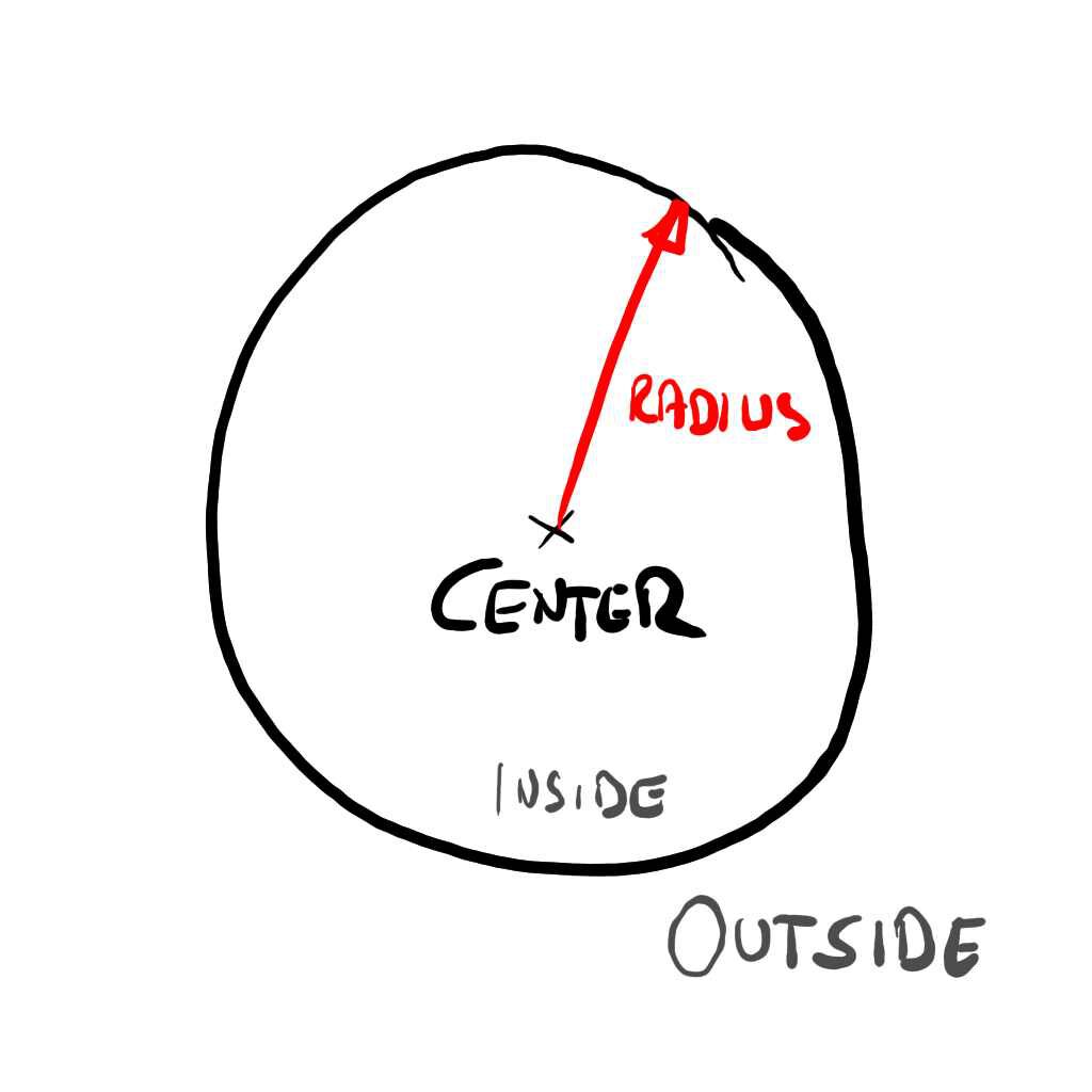
Finding where the sphere is at and its dimensions – easy. It’s just defined by a position and a radius.
Knowing if you are inside or outside – also easy.
Any point which is further apart from the center than the radius, is outside.
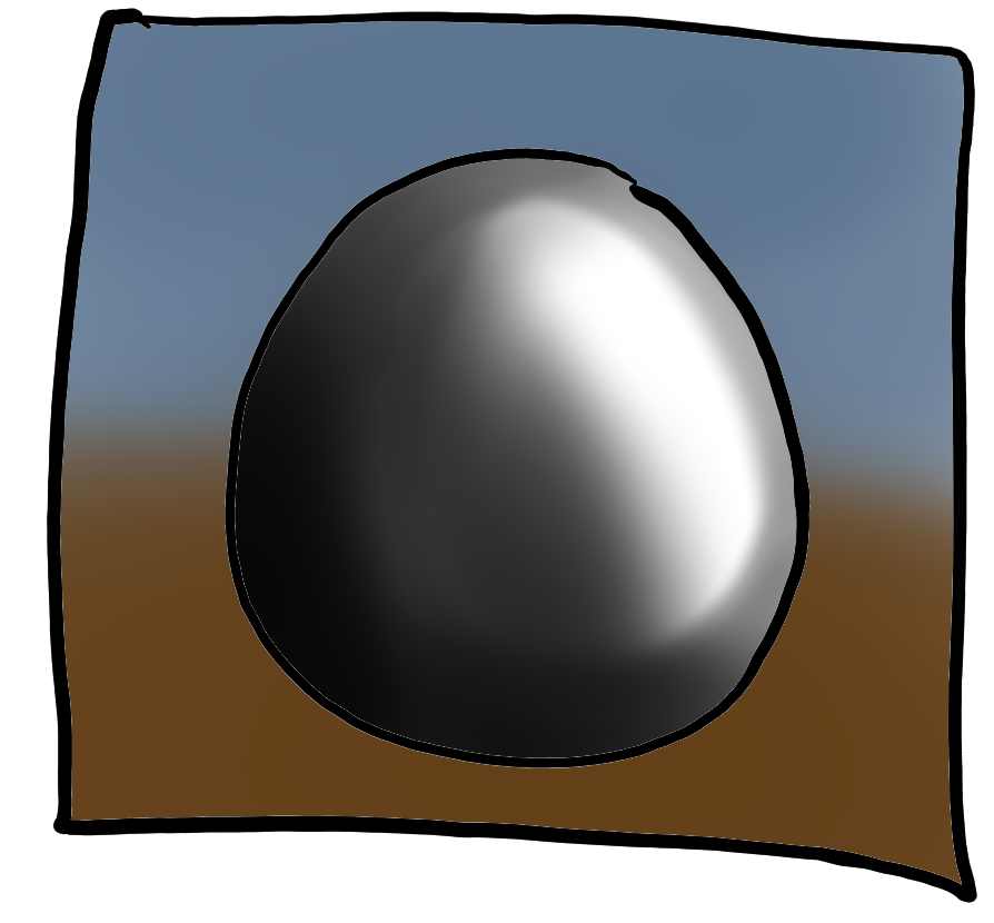
The actual render shape of the sphere is… well… a sphere.
Since I am using unity, it’s just a game object with the default sphere mesh. Anything interesting will happen inside of that.
Just plugging the default shader, you get – no surprises here – a solidly shaded sphere.
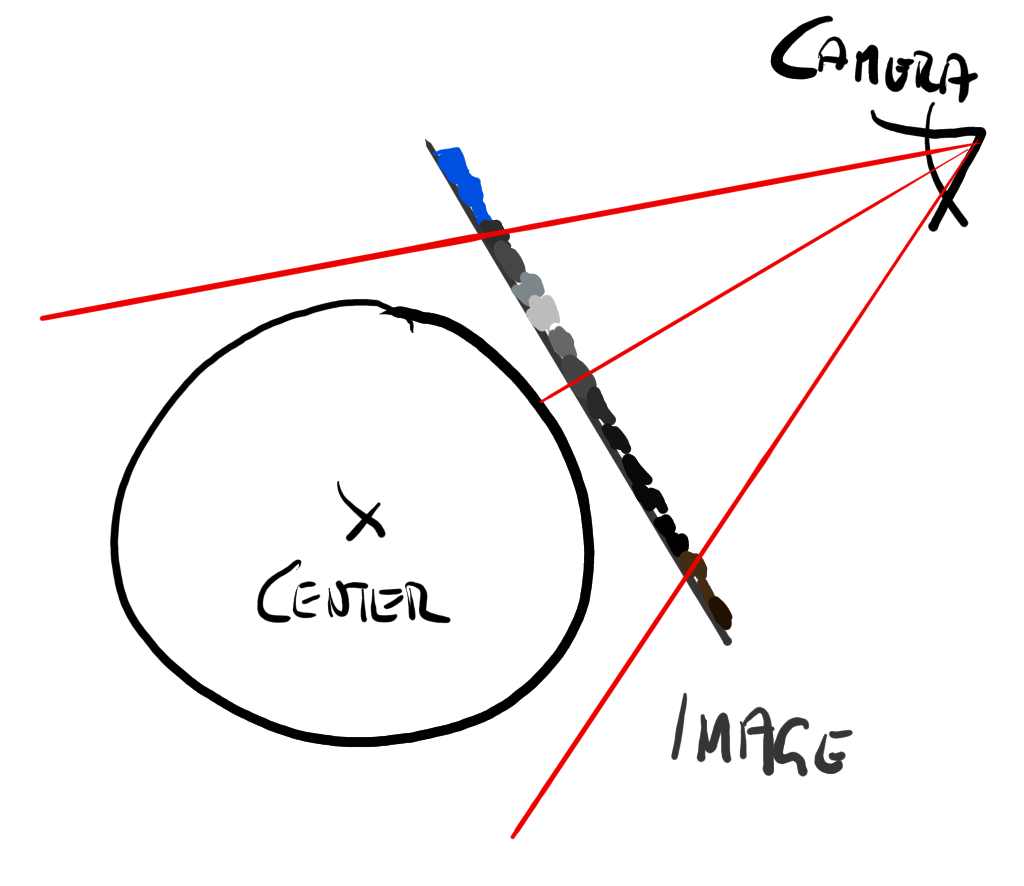
Now looking at this a little closer, what is actually happening is this:
The render engine rasterizes the surface of the sphere mesh through the camera view. We end up with every pixel that is covering the sphere being shaded by its material shader – which by default is usually some matte solid gray.
The following image shows all the interesting bits involved in that process.
Now I won’t go into all the details that are involved with an entire rasterizer pipeline. There is plenty of reading on the internet, that will explain it at length a lot better than I can scribble down here.
But in essence our problem boils down to what color we should give those pixels in Figure 4, so the sphere looks from our camera as if it’s transparent with something inside of it that resembles a sloshing liquid.
Emulated Liquid
Before we – quite literally – peek into the sphere, let’s talk about emulating a liquid. What we are after is a function, that tells us if a point inside the sphere is either part of the liquid or not.
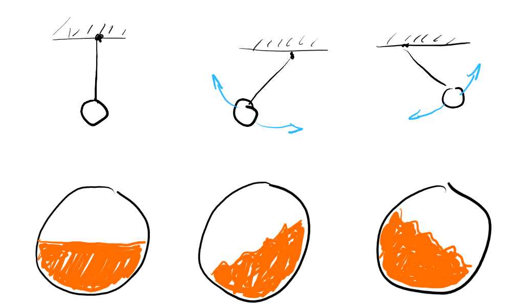
First step for this is to establish a flat liquid level, that tells us how much liquid is inside the container.
Any point below the liquid level will be inside of the liquid, any point above is outside.
There are a few things we can assume about how any liquid behaves, when trapped in a glass ball.
It will naturally slosh around with the momentum of the movement of its container but will dampen down and level out again after being static for a while.
To emulate momentum and dampening I went and implemented a little imaginary pendulum.
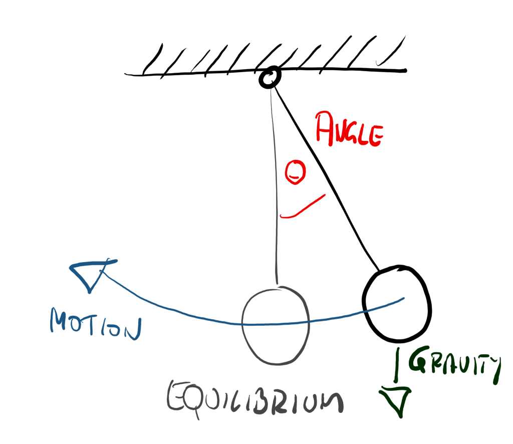
This pendulum constantly evaluates and with every movement of the container in my game setup, I pull out the imaginary ball from its rest point by applying an imaginary force in the opposite direction.
So moving the container will pull it out and over time it will swing back and forth until coming to rest.
Luckily the math of pendulums isn’t very hard, so I’d refer you to the details somewhere on YouTube.
For keeping it simple, I left the pendulum to be a simple 2D representation, so a single angular value θ tells me how far it’s away from it’s equilibrium.
This is the first property driving my shader, which schematically looks kinda like this.
It happens that the sloshing liquid itself seems to be somewhat related to the direction of the container’s movement as well.
If I move the container left/right, the liquid sloshes right/left. If I move it forward/back, the container moves back/forward. See that the sloshing always happens around an axis perpendicular to the movement direction.
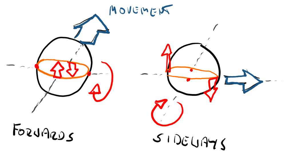
movement in respective forward axis
I capture this in a second property with an accumulated and slightly dampened velocity of the container.
Now looking at liquids in containers, we kinda notice that apart from the momentum and the dampening, the movement – while complex – is also somewhat nondescript and – well – “sloshy”. There is so much physics going on, that the actual shape is increasingly indiscernible the more it moves.
This we can turn to our advantage to add the last missing part to the surface description, some liquid-esk surface distortion.
To emulate this distorted liquid surface, I just stacked a bunch of trigonometric functions on top of each other. In this case I used three.
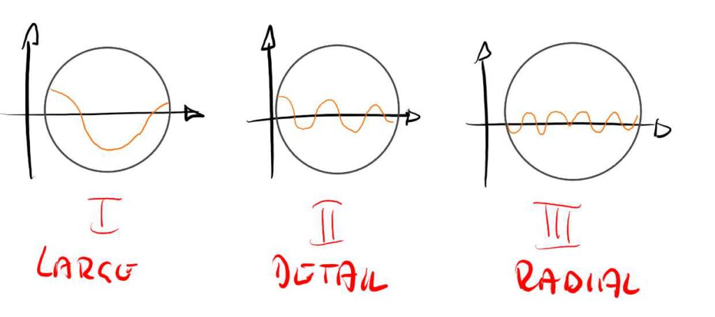
The first layer is a basic sinus function across the world position in x and z.
The second layer is also a sinus function with a higher frequency for some smaller ripples.
The third layer is a sinus function based on the distance to the center of the sphere. This makes it look a little like there are tiny waves bouncing off its sides.
The involved base frequencies and amplitudes for those functions are literally magic numbers that I obtained with good old trial and error until I liked the result (and ran out of time).
Not to forget that their amplitude is multiplied by the speed of motion/extend of pendulum angle, to make large movements make large waves and vice versa.
All three functions also have a time-based offsets, to make the waves evolve over time. So the current game time is another property used by the shader.
The liquid level, the pendulum and movement based sloshing as well as the fake stack of waves all contribute to a function called liquid(…), which returns the height of the liquid at any given world position. No magic happens there, it’s really just the sum of all the contributing parts.
Raymarching
We now know all about our sphere and we can analytically describe how the liquid looks on its inside.
We have a value that tells us how much the liquid is sloshing (pendulum angle) and also which direction the movement of the container goes (container velocity).
So lets look how we figure out how to make use of that.
At the core of the shader is something called a ray marcher.
It’s a common principle – again Google will help, but essentially I’m following the gaze of the camera through the rasterized pixel into the inside of the sphere.
Luckily a sphere is wonderfully simple to ray march, as we can find the in and out point reliably and fast, and keep the number of steps reasonable.
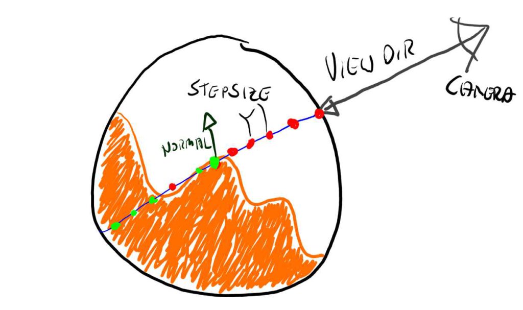
As shown in the picture we are marching along the view ray from the camera through the fragment position into the volume of the sphere.
Each point on the way we are evaluating our liquid function to find out if we have crossed over from the outside to the inside of the liquid.
If we have so, then we have hit our actual surface. Bingo!
In case your liquid is not see-through (which is easier!) – you can stop here. Otherwise there is a bit of logic needed to define how transparent the liquid is and how to accumulate that density over distance while stepping all the way to the other end of the sphere.
The last thing missing is to sample the surroundings of the first hit point to calculate a new normal to use for the actual surface shading part that calculates lights etc.
Conclusion
Well I do those things from time to time, when i get inspired by something that I find in one of the many streams of the internet – and try it out myself just to wrap my head around what’s involved.
The main learnings from this excercise are the interesting amount of hackery you can get away with in a system like this, as well as some more boilerplate insights in coding surface shaders with to be used in Unity.
I hope this write-up was somewhat informative, if you have any questions/commentary or want more of this kind of write-ups, please hit me up on twitter @richterteer.
And now, slosh, slosh away!